Breakout board for Anytone AT-D868UV external mic and speaker
In the fall of 2018 I got a DMR radio, the Anytone AT-D868UV, for amateur radio use. Although it’s a rugged handheld radio, my primary use is at my desk in the home office.
For this use case, a separate microphone is handy to avoid needing to hold the radio or press the less-than-ergonomic PTT button. There are plenty of speaker-mics and headsets available for the Kenwood type connecton on the radio, but I wasn’t really interested in that. I have a good Elecraft MH3 microphone and plenty of headphones and speakers around the house. I didn’t want to spend the money on new hardware when I had perfectly good items already. When traveling, I’d also like to share one mic and speaker set with my other radios.
So I decided that I needed to find a way to make my microphone and an existing speaker place nice.
Step 1: Build a prototype
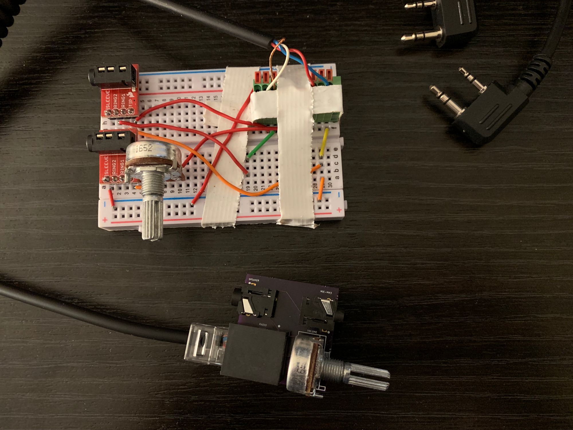
With a bit of research about the radio and mic connections, I was able to cobble together a circuit to connect them all together. This site was helpful for the Anytone connection, and this blog post was helpful for the microphone.
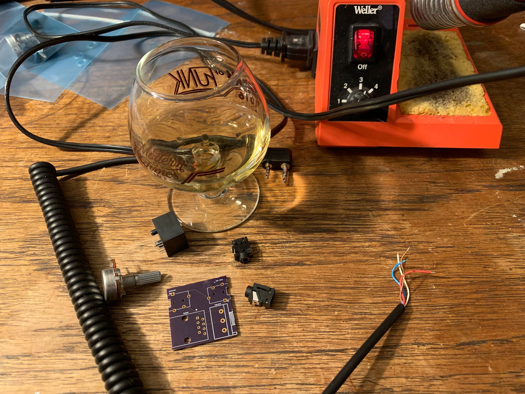
I didn’t have a Kenwood connector sitting around nor was I able to quickly find any, so I opted to get some 3.5mm and 2.5mm TRS audio plugs to do initial prototyping with. It was a bit janky, but it worked to prove the plan.
I eventually found this 2-pack of Kenwood style connection cables on Amazon. It turns out the keywords to find that were not the most obvious. Pro tip: search for “replacement cables” and “kenwood 2 pin”.
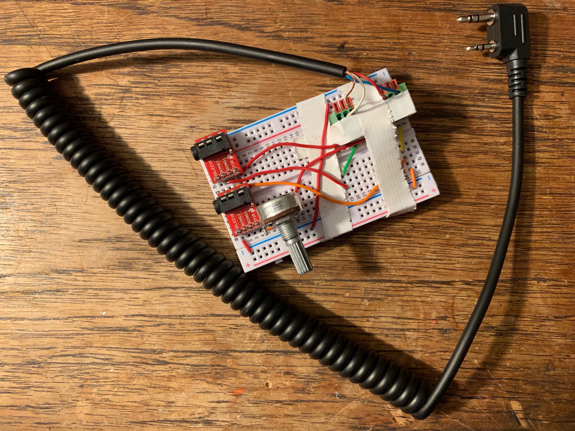
As you can see, I also added a potentiometer to adjust the speaker volume. The radio has a loud internal speaker and it puts out just as much of a punch on the headphone line. By default the volume knob on the radio, when at the lowest setting, was still way too loud. You can adjust the maximum volume output in the radio settings, which adjusts all of the volume steps too, but I still wasn’t a fan of the granularity of the steps available using just the radio adjustments. The potentiometer helped immensely.
I used the prototype for a bit and decided it was a success. It was time to move on to the next step.
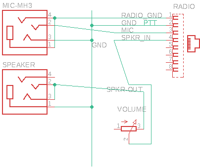
Step 2: Schematic
At this point, I decided that I wanted to make this a little more lasting than just the breadboarded prototype. It had been quite a long time since I had designed a schematic and I had never laid out a PCB. What better time than the present to give it a go?
I fired up the free version of EAGLE and did my best to remember anything from the electronics class I had in college.
It did take me a while to figure out the right way to load in the components I was thinking about using. My first pass used whatever generic componets I could find in the libraries that come with EAGLE. With some searching I found online sources for the components I was going to buy.
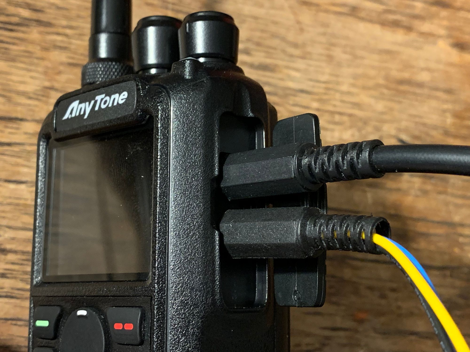
During schematic design I also decided to make the radio connection an RJ-45 connector instead of directly soldering the wires from the Kenwood connector to the board. I wanted this breakout to be somewhat portable and reusable. Having a long wire hanging out of it felt like an annoyance, especially if I wanted to ever adjust how I was connecting to the radio. I also thought that perhaps this setup could be useful for other radios (such as my Yaesu FT2DR) too with just a change of the radio plug.
Step 3: Board Layout
At this point I was totally and completely out of my knowledge area. Time to learn.
I dug around Digi-Key to find the parts I would use for this. I selected them based on cost and whether I could find layout, footprint, and 3D model files for the component. Most of the time Digi-Key product pages linked to those useful files, and if not I just looked for them on SnapEDA directly.
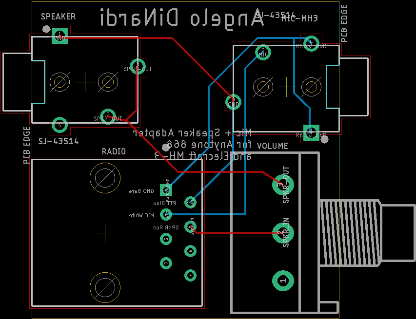
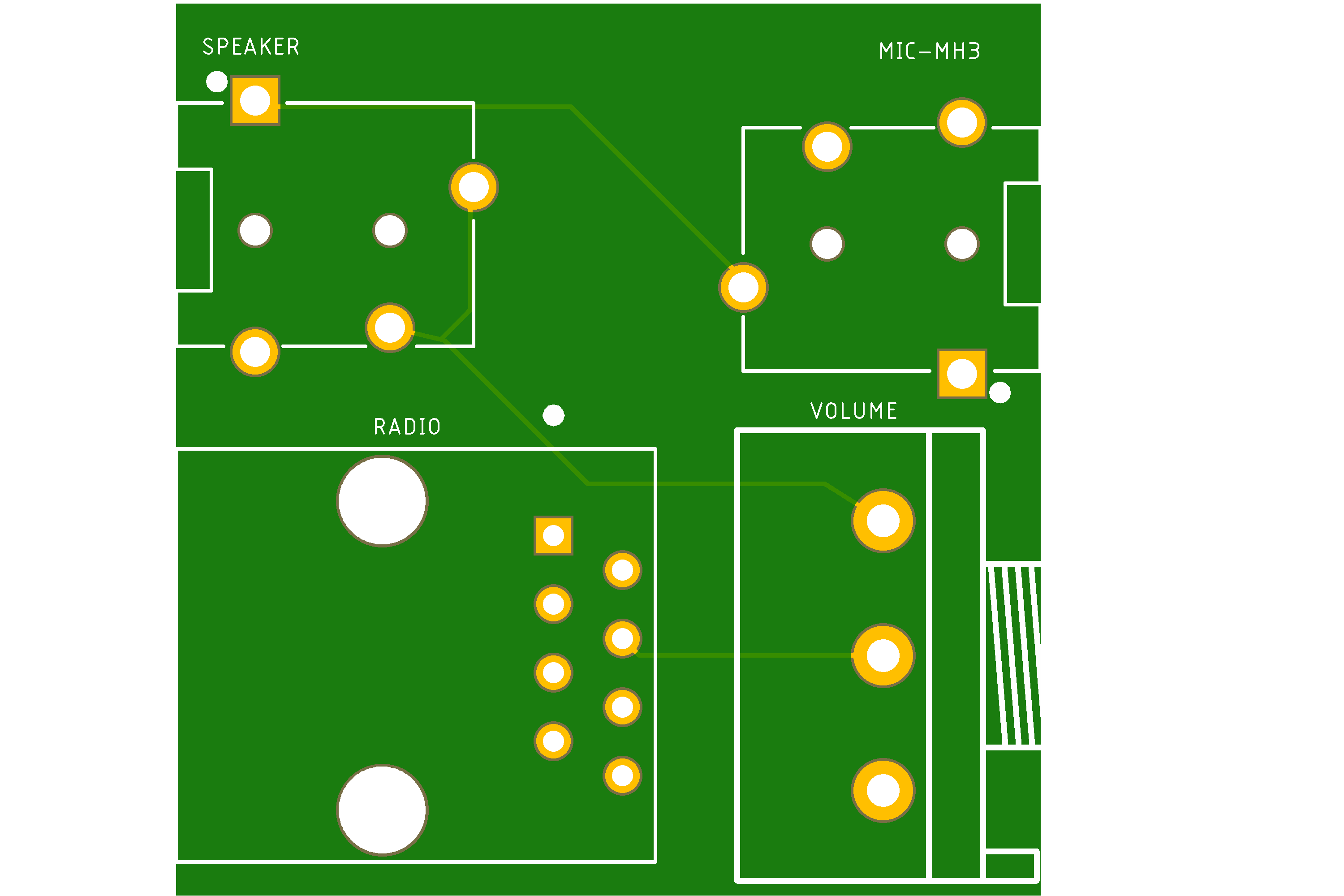
After much playing around, I found (what I thought) was a pretty tight board layout that packed all the parts together in a useful way.
Step 4: PCBs
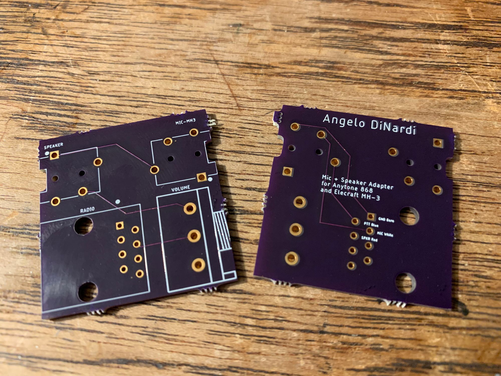
I ordered the PCBs from OSH Park. They had a good balance of cost, turn-around time, reputation, simplicity, and capabilities for what I needed. Being my first set of boards, ever, I wasn’t really picky.
Step 5: Assembly
A little solder and scotch was all that was needed to assemble this project. The right ratio of scotch to solder is important, otherwise the results could be quite painful.

Once assembled, I plugged it all in and gave it a test run. I was able to key up and the radio began transmitting – but my voice wasn’t being transmitted. Well crap.
After staring at the board, the schematic, and my prototype I realized that I missed two connections on the prototype when I made the schematic. Turns out I had done such a good job neatly hiding some of the wiring under other components on the breadboard that I forgot they existed. Oops.
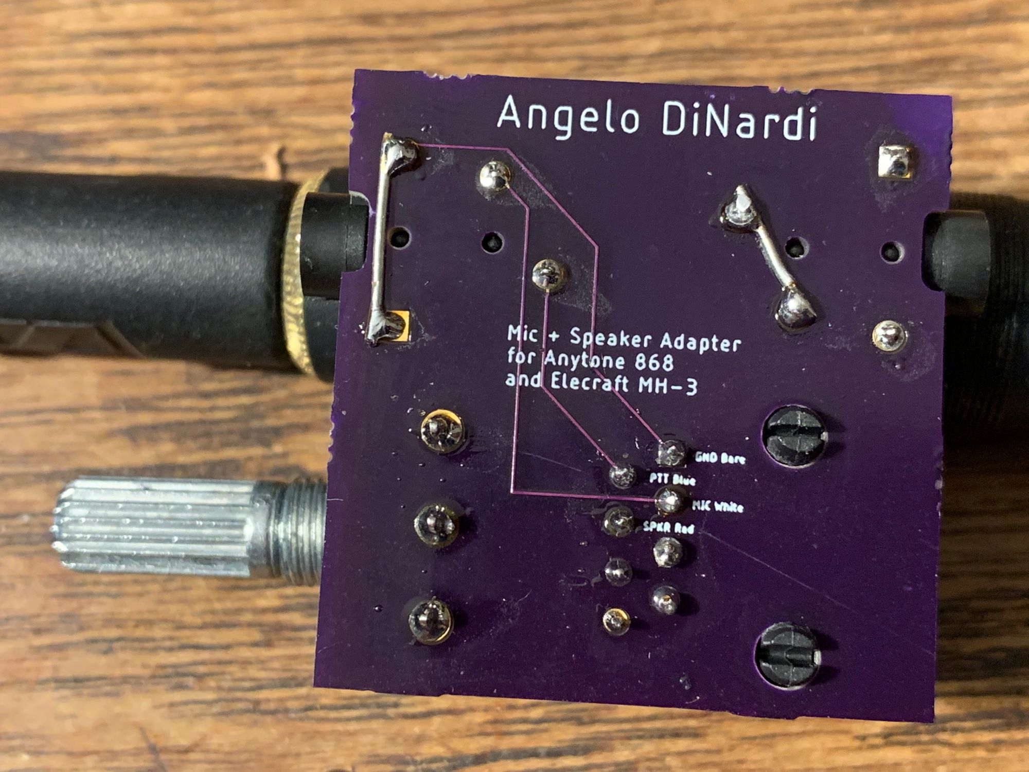
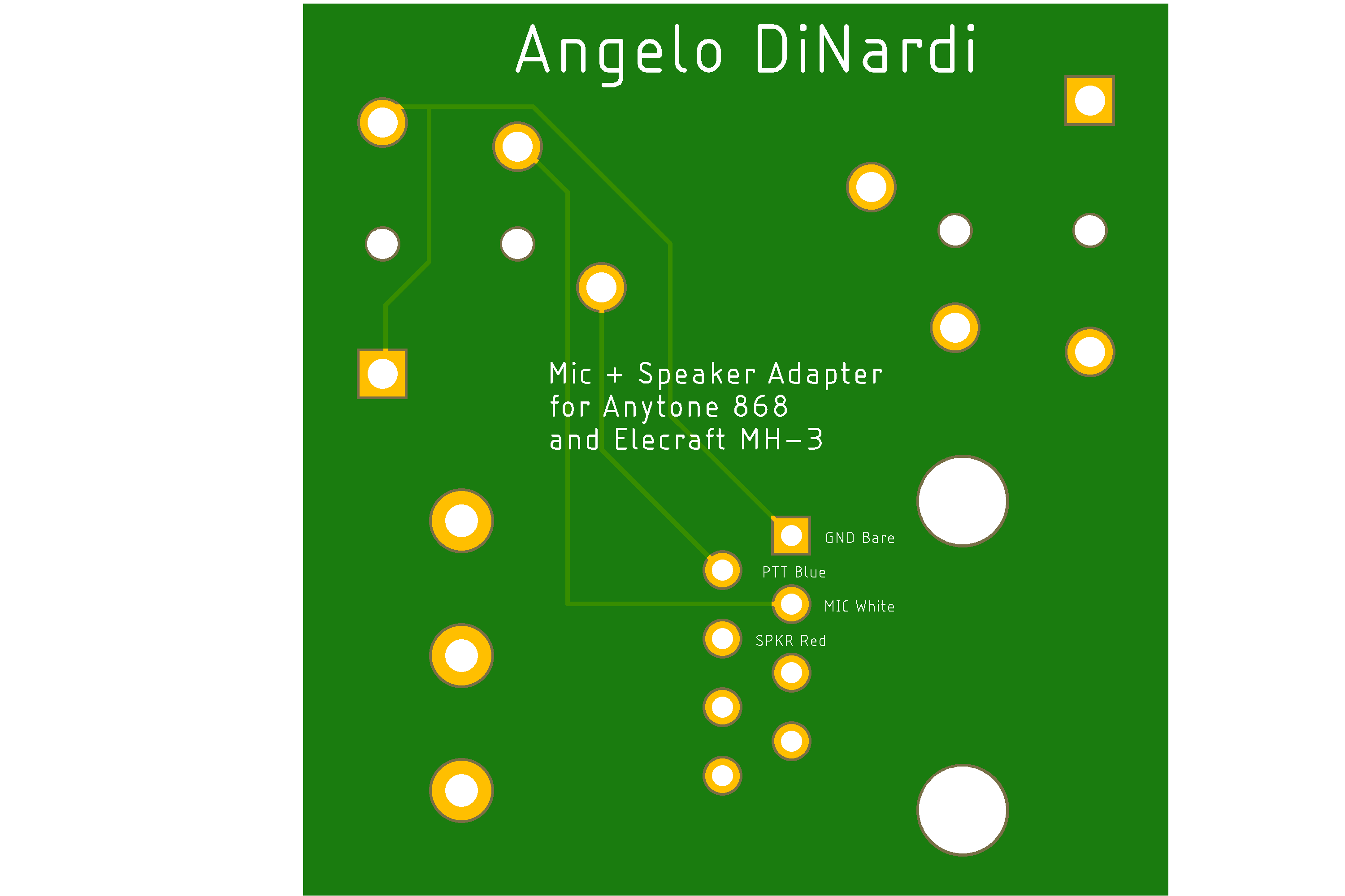
The schematic (and board layout) missed the microphone ground connection. I had only grounded PTT (which is why I was able to key up). I also missed the speaker connection to link the left and right channels together to make a single mono output. It was a quick fix with some wire to bridge the terminals on the board.
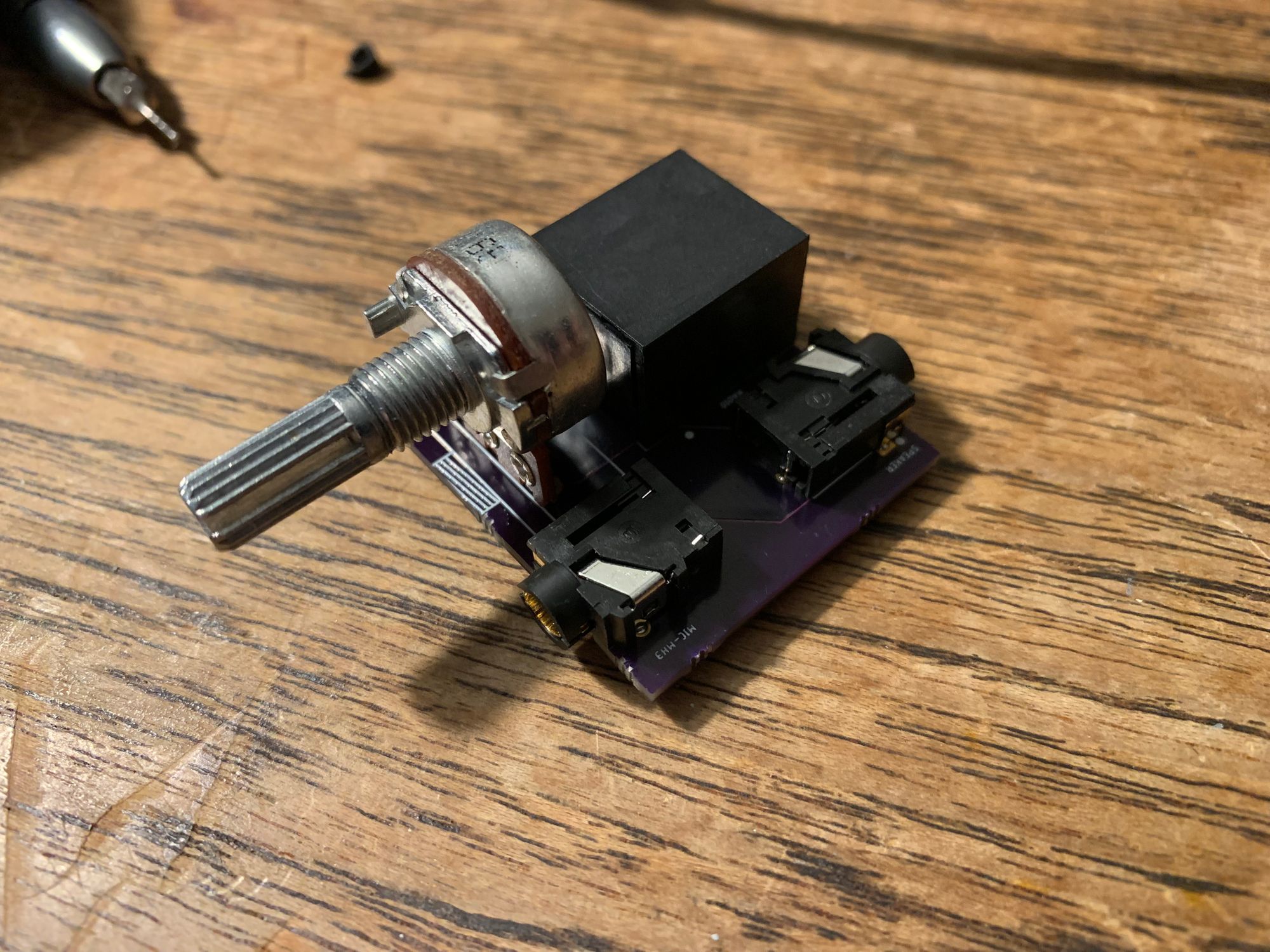
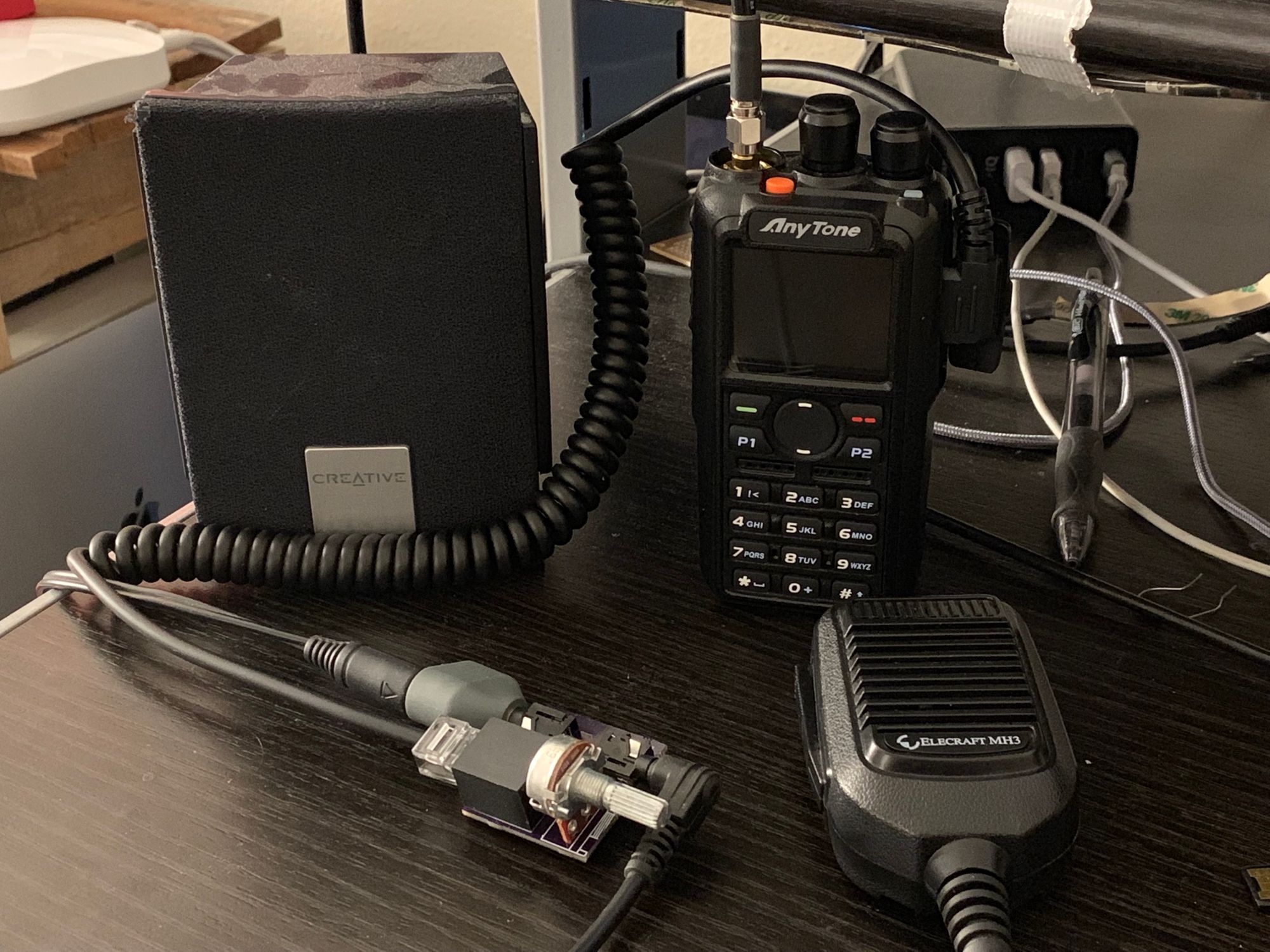
Step 6: It’s alive!
So far, this little adapter is working well. No longer am I worried about yanking wires apart when using my radio.
The End
It isn’t perfect, but it’s wonderfully usable. It was a relatively simple project to break in to creating a schematic, board layout, and getting a PCB made.
I was disappointed when it seemed like my options were to buy an off-the-shelf speaker-mic or headset. Separating the speaker and mic for desk-use feels a lot more natural – and now I can also connect the radio to an external antenna during use!
This implementation is pretty specific to the MH3 microphone, but the concept could be adapted to any number of other microphones and radios. I hope someone else finds inspiration or help to build their own homebrew radio project to solve a problem they’re having.
Update: April 24, 2019
For anyone wanting to build this yourself, here are links to OSH Park and Digi-Key to order your own parts. The PCB is an updated version with the fix mentioned above already included in the design.
![]()